Solidworks Mold Design
Course Overview
DESCRIPTION
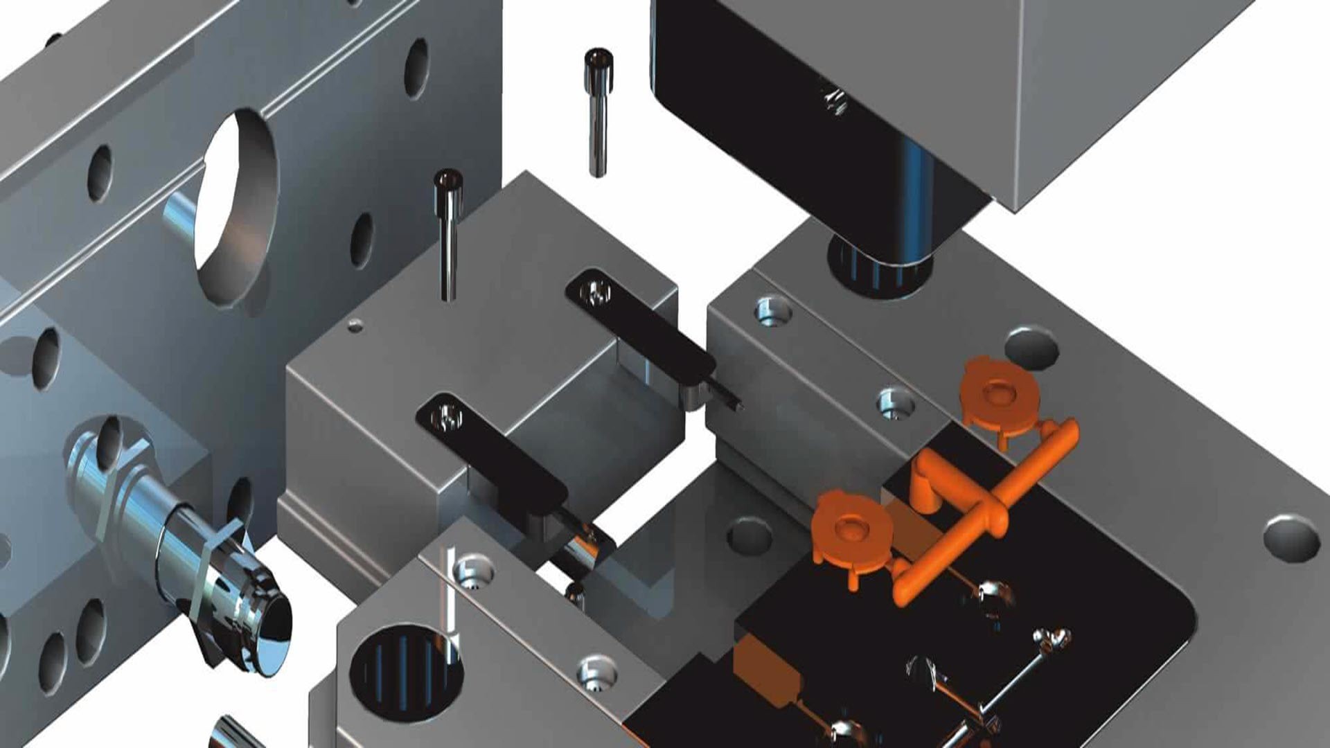
The SOLIDWORKS Mold Design course teaches you how to quickly generate tooling for any given part and separate it into core and cavity components (or punch and die for Tool and Die applications).
This knowledge is very valuable for most mechanical designers, especially designers of molds, embossing dies, nests, and welding/checking fixtures.
You will also learn to use analysis tools for developing optimal parting lines, troubleshooting draft and undercut issues, plus importing and repairing third party geometry.
REQUIREMENTS
- Completed the SOLIDWORKS Advanced Part Modeling course
- At least 1 month using software
- Able to take time out for training
FEATURES TARGETED
- Molding Tools
- Draft Analysis
- Surface creation and editing tools
SKILLS YOU WILL ACQUIRE
- Able to create a complete Mold
- Able to create Library Features
- Able to diagnose and repair errors
LEARNING OUTCOMES
- Create mold assemblies derived from your part designs
- Automate the production of the mold to save you design time
- Incorporate lifters, side cores and core pins in your mold design
- Design Electrodes for your molds
<p>• Core and Cavity Mold Design</p>
<p>• SOLIDWORKS Mold Tools</p>
<p>• Problematic File Translations</p>
<p>• Mold Analysis Tools</p>
<p>• Analyzing Draft on a Model</p>
<p>• Draft Analysis Colors</p>
<p>• Adding Draft</p>
<p>• Scale the Part to Allow for Shrinkage</p>
<p>• Determine the Parting Lines</p>
<p>• Manual Selection of Parting Lines</p>
<p>• Automation</p>
<p>• Modeling the Parting Surfaces</p>
<p>• Smoothing the Parting Surface</p>
<p>• Surface Bodies</p>
<p>• Interlocking the Mold Tooling</p>
<p>• Creating the Mold Tooling</p>
<p>• Multiple Parting Directions</p>
<p>• Trapped Molding Areas</p>
<p>• Side Cores</p>
<p>• Lifters</p>
<p>• Core Pins</p>
<p>• Case Study: Electrode Design</p>
<p>• Electrode Clearances</p>
<p>• Keeping the Sharp Edges</p>
<p>• Beyond the Basics</p>
<p>• Importing Data</p>
<p>• 3D Model Types</p>
<p>• Definitions</p>
<p>• Case Study: Solids vs. Surfaces</p>
<p>• Terminology</p>
<p>• File Translators</p>
<p>• Modeling Systems</p>
<p>• File Translation</p>
<p>• Why Do Imports Fail?</p>
<p>• Diagnosis and Repair</p>
<p>• Case Study: Repairing and Editing Imported Geometry</p>
<p>• Checking Solid Bodies</p>
<p>• Making Copies of Faces</p>
<p>• Case Study: Import Diagnostics</p>
<p>• Repairing Gaps</p>
<p>• Repairing Faces</p>
<p>• Case Study: Mixer Base</p>
<p>• Draft Analysis Options</p>
<p>• Parting Line</p>
<p>• Core and Cavity Surfaces</p>
<p>• Shut-Off Surfaces</p>
<p>• Parting Surface</p>
<p>• Tooling Split</p>
<p>• Seeing Inside the Mold</p>
<p>• Case Study: Splitting a Part</p>
<p>• Case Study: Plastic Bezel of a Cordless Drill</p>
<p>• Creating New Drafted Faces • Interlock Surfaces</p>
<p>• Surfaces in Mold Making</p>
<p>• Case Study: Router Bottom</p>
<p>• The Mixer • Case Study: Mixer Handle</p>
<p>• Case Study: Manual Parting Surface</p>
<p>• Reusing Data • Design Library</p>
<p>• Task Pane</p>
<p>• 3D Content Central</p>
<p>• Library Features</p>
<p>• Creating a Library Feature</p>
<p>• Configurations in Library Features</p>
<p>• Case Study: Water Line</p>
<p>• Smart Components</p>
<p>• Using Combine and Split</p>
<p>• Creating a Cavity</p>
<p>• Using Surfaces</p>
<p>• Using the Up to Surface Method</p>
<p>• Using the Split Method</p>
<p>• Manually Creating Shut-off Surfaces</p>